Jiangsu Xindake Connection Technology Co., Ltd. offers you free information and the latest news on battery connectors, battery pack inserts, e-bike battery nickel strips, nickel-plated strips and more. Stay tuned!
Jiangsu Xindake Connection Technology Co., Ltd. offers you free information and the latest news on battery connectors, battery pack inserts, e-bike battery nickel strips, nickel-plated strips and more. Stay tuned!


Copper has conductive properties. We often see copper wires being used in power systems, so what about the role of copper busbars? In fact, copper busbars are the same; their function is to conduct electricity. So how are copper busbars created, and what are the points to pay attention to in the process?Copper bus manufacturerLet me tell you.
1. Prepare everything needed to make the busbar to minimize errors in its production.
2. The accounting for cutting copper busbars makes full use of the Pythagorean theorem.
3. When calculating copper busbars, attention should be paid to adding or subtracting the busbar thickness to reduce manufacturing errors.
4. When cutting copper busbars, consider the reasonable routing of the copper busbars inside the cabinet.
5. The accounting for the cutting of the main copper busbar should make full use of the cabinet division line.
6. When calculating copper busbars, pay attention to whether the tape measure starts from 100mm; subtract 100mm of error during calculation.
7. When cutting copper busbars, consider whether there is scrap material that can be reused.
8. Gloves should be worn during processing of copper busbars to prevent oxidation.
9. Copper busbar punching should be sampled and punched.
10. When marking copper busbars, the square ruler used should be pressed tightly against the busbar.
11. When bending copper busbars, consider the bending spacing allowed by the busbar machine of 50mm.
12. Placement of busbars (based on the direction of importance of the cabinet when facing the panel). The placement of A, B, C (yellow, green, red) phases is from top to bottom; from inside to outside; from left to right. The neutral bus N row and the grounding bus PE row are at the bottom of the cabinet, with the grounding wire in front and the neutral wire behind.
13. The electrical gap between phases should be kept above 20mm; if less than 20mm, use a partition for blocking.
14. Busbar fixing members should meet the requirements of 3C.
15. The placement inside the main busbar cabinet should be as simple and flow-free as possible, with the bent points kept convergent, and the bends should be arranged 30mm at the connecting row for a more attractive contrast.
16. When the on-site busbar serves as the cabinet incoming line, it is the upper inlet line of the cabinet. The incoming end of the structural circuit breaker should be led 200mm out of the cabinet top to facilitate on-site copper busbar connection, and the N busbar should also be led out together.
17. If the on-site cable serves as the cabinet's incoming line, it should enter from the bottom of the cabinet. The incoming end of the structural circuit breaker should be directed downward, and the spacing between the outgoing copper busbars should be greater than 50mm to facilitate on-site cable connection. The number of cable connection holes is determined according to the rated current of the structural circuit breaker, with one hole punched for every 500A; for example, a 2000A breaker would require four holes.
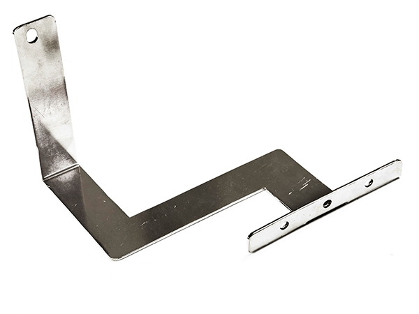
18. The diameter of holes must not exceed half the width of the copper busbar. Processing must ensure accurate and straight positioning, not tilted, and the spacing between holes should not exceed 0.5mm.
19. The control panel should be made of Φ8 round tube or 15*5 rectangular copper busbar; the round tube must be fitted with heat shrink tubes; The rectangular control panel should be installed with cabinet sections and connected.
20. The bending angle of the copper busbar must not be less than 90°. After forming, there should be no cracks or wrinkles at the bends, and the unevenness should not exceed 1mm.
21. Rectangular copper busbars should be cold-bended, not hot-bending.
22. Copper busbars should minimize right-angle bends; bends must not have cracks or noticeable wrinkles. The bending degree of multi-piece busbars should be uniform.
23. When the copper busbar changes 90°, the length of the changed part should be 2.5-5 times the width of the busbar.
24. Lap joint connection of rectangular busbars: It should meet the requirements of the following Table 3; when the busbar is connected to the equipment terminal, it should meet the requirements of the current standard "Connection Terminals of Transformers, High-Voltage Apparatus, and Bushings".
25. The operation table frame should have a grounding copper busbar no smaller than 2mm × 15mm.
26. Terminals on the grounding copper busbar may share one grounding screw for multiple wires.
27. The cross-sectional area of the grounding busbar and grounding wire is 1/2~1/4 of the cross-section of the main circuit copper busbar and conductor.
As shown by the above information, the process of forming copper busbars is quite complicated. Drawing lines must be precise, bending must consider bendability and have certain limitations, and so on. If you want to learn more, you can contact Yixing Xindake New Energy Technology Co., Ltd. It offers relatively favorable prices for stamping parts processing and is a professional copper busbar manufacturer producing high and low voltage components, such as copper foil flexible connectors and stamped parts. We welcome your inquiry.
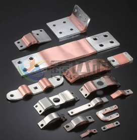
Copper and aluminum busbars are widely used in battery packs. Nowadays, the busbars are mostly made of multilayer copper foil/aluminum foil laminates as the base material, and are fabricated through a...
2026-08-05 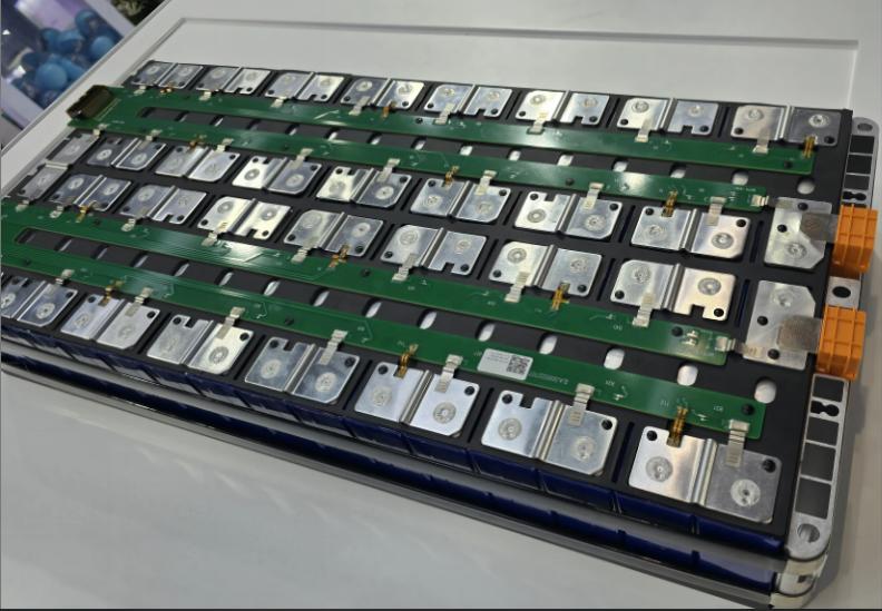
The CCS integrated busbar is mainly composed of signal acquisition components (such as FPC, PCB, FFC, etc.), plastic structural parts, nickel strips, copper busbars, aluminum busbars, etc. These are c...
2025-08-15 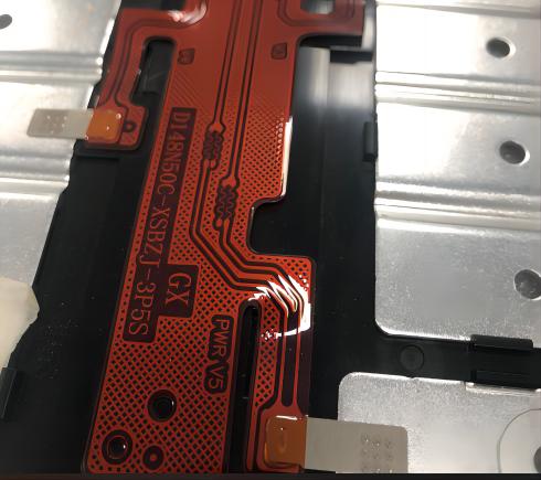
Nickel is a metal with significant industrial value, with a melting point of 1453°C, a boiling point of 3075°C, and a specific gravity of 8.8 g/cm³. It has excellent corrosion resistance, is not easil...
2025-08-15 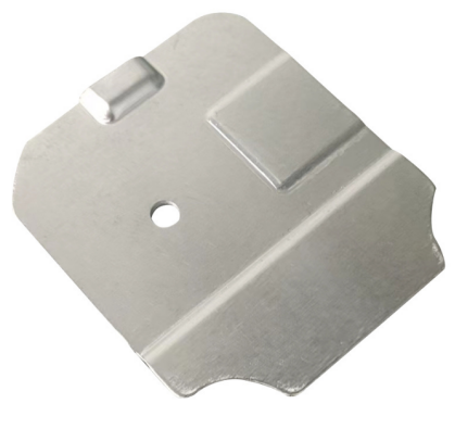
Product Name: Power battery soft aluminum busbar, battery module welding flexible connector aluminum busbar, battery soft aluminum busbar Product Material: 1060 O-temper aluminum foil strip, aluminum ...
2023-05-04Phone:
0510-87183933