Jiangsu Xindake Connection Technology Co., Ltd. offers you free information and the latest news on battery connectors, battery pack inserts, e-bike battery nickel strips, nickel-plated strips and more. Stay tuned!
Jiangsu Xindake Connection Technology Co., Ltd. offers you free information and the latest news on battery connectors, battery pack inserts, e-bike battery nickel strips, nickel-plated strips and more. Stay tuned!


Copper bus manufacturerExplaining the power system of a car for you, without a power system, a car cannot move. Let me tell you, whether a car is serviced annually or every four years, it's not only to check those brake components and the engine, but also to ensure the car has sufficient electrical power. The power battery system refers to a type of energy storage device used to provide energy for the drive of an electric vehicle, consisting of one or more battery packs and a battery management (control) system. The design of the power battery system should be based on meeting the vehicle's power requirements and other design considerations, while also taking into account the internal structure, safety, and management design of the battery system itself.
For example, vehicle manufacturers will determine a limited space for the power battery system for the vehicle to be designed after considering related requirements such as safety design, wiring harness connection design, and connector design. Then, within the constraints of this limited space, they will arrange the battery modules, battery management system, thermal management system, and high-voltage system, ensuring uniform heat dissipation for battery cells and modules, maintaining battery consistency, and improving the lifespan and safety of the battery system. Some overall and general principles to consider during design include good safety, high specific energy, high specific power, strong temperature adaptability, long service life, ease of installation and maintenance, and low overall cost.
Due to the differences in the structure and operating modes of different types of electric vehicles, the performance requirements for power batteries also vary. Pure electric vehicles rely entirely on the energy from the power battery system for driving. The larger the battery system's capacity, the longer the driving range, but the required battery system's volume and weight also increase. Although hybrid vehicles have lower capacity requirements for the power battery system compared to pure electric vehicles, they need to be able to provide high instantaneous power at certain times. Moreover, series and parallel hybrid vehicles have different requirements for the battery system.

A typical power battery system
Therefore, the design process of the power battery system is generally as follows:
(1) First, determine the design requirements of the whole vehicle.
(2) Then determine the vehicle's power and energy requirements;
(3) Select the most suitable cell that can be matched;
(4) Determine the modular structural form of the battery module;
(5) Determine the design requirements of the battery management system and the thermal management system;
(6) Simulation modeling and specific experimental verification.
As an important component of electric vehicles, the power battery system is discussed below mainly in terms of its specific structure and functions. It is divided into four main parts: battery module, battery management system, thermal management system, and electrical and mechanical systems.
1. Structure and design of battery modules
A power battery module refers to an assembly in which individual power battery cells are combined in series and parallel, equipped with a protection circuit board and casing, capable of directly supplying electrical energy. It is one of the secondary structures that make up a power battery system. Individual power battery cells, also known as battery cells, are mainly categorized by cathode material, including lithium cobalt oxide, lithium manganese oxide, lithium iron phosphate, and ternary materials such as nickel-cobalt-manganese oxide. According to the information collected, the basic properties of cells made from different materials are shown in the table below.

Based on the structural shape of the cells, they are mainly divided into cylindrical cells, prismatic cells, and pouch cells, each of which has very distinct advantages and disadvantages. To a certain extent, the performance of the cells determines the performance of the battery module, which in turn affects the performance of the entire power battery system. Therefore, when designing a power battery system, it is necessary to select the cell materials and shapes according to the design requirements of the vehicle.

First, the capacity of the battery system should be determined based on the power requirements of the electric vehicle and the power consumption, time, and operating temperature required by various high-voltage components. Then, when designing the battery module, the characteristics of the power battery must be considered, because the output/input of the power battery changes at different temperatures. Capacity and output performance gradually degrade over time. If there is a design error in battery performance or selection, it will not meet acceleration and hill climbing performance at low temperatures, and battery aging will also affect system performance. The battery module is composed of multiple power cells connected in series and parallel, including individual cells, fixed frames, electrical connection devices, as well as temperature sensors and voltage detection circuits.

Structure design process of power battery system (cell → module → system)
When designing the battery module in conjunction with overall vehicle design requirements, the battery module design needs to consider the following aspects:
· The fixed connection method for battery groups should be based on the overall requirements of the power battery system design, and the selected cell structure shape.
· The assembly of battery modules requires moderate tightness, with all structural components having sufficient strength to prevent deformation or failure caused by internal and external forces in the battery.
· The cell and battery module must have dedicated fixing devices, a compact structure, and ventilation and cooling channels should be set according to the heat dissipation of the battery box.
· The conductive connection distance between individual cells should be as short as possible, ensuring reliable connections and flexible connectors. The conductivity of each connection point should meet the high overcurrent capacity of electrical equipment.
· Fully consider insulation protection issues between battery series-parallel high-voltage connections, such as insulation gaps and creepage distances.


Battery modules with square cells and cylindrical cells
2. Design of the Battery Management System
Battery Management System (BMS), that is, Battery Management System, determines the status of the entire battery system by detecting the state of each individual battery in the battery pack, and carries out corresponding control adjustments and strategy implementation on the power battery system according to their status, achieving charge and discharge management of the power battery system and each individual battery to ensure the safe and stable operation of the power battery system. The basic functions of the battery management system can be divided into three major parts: detection, management, and protection. Specifically, it includes functions such as data acquisition, status monitoring, balance control, thermal management, safety protection, and information management.

Battery Management System
The battery management system can be divided into two main hardware modules: the master module and the slave control module. It mainly consists of a data acquisition unit (acquisition module), a central processing unit (master control module), a display unit, a balancing unit detection module (current sensor, voltage sensor, temperature sensor, leakage detection), and control components (fuse device, relay), among others. The central processing unit is composed of a high-voltage control circuit, a master control board, etc., while the data acquisition unit consists of modules such as the temperature acquisition module and the voltage acquisition module. Generally, CAN fieldbus technology is used to achieve communication between them.
The software design functions in a power battery management system generally include voltage detection, temperature acquisition, current detection, insulation detection, SOC estimation, CAN communication, discharge balancing, system self-check, system monitoring, charging management, and thermal management. The overall design indicators include high measurable total voltage, large measurable current, SOC estimation error, individual cell voltage measurement accuracy, current measurement accuracy, temperature measurement accuracy, operating temperature range, CAN communication, fault diagnosis, fault memory function, online monitoring, and debugging capabilities.
The BMS communicates with the vehicle controller, motor controller, energy management system, onboard display system, etc., through a communication interface. The overall working process is roughly as follows: first, the data acquisition module collects data such as the battery's current, voltage, and temperature → then the collected data is sent to the main control module → the main control module analyzes and processes the data, and issues corresponding program control and modification instructions → the respective modules take corresponding measures to regulate the battery system or battery, while simultaneously sending real-time data to the display unit module.
In terms of technical requirements for the battery management system, relevant standards must be met, such as QC/T 897-2011:
·The insulation resistance between the live parts connected to the battery management system and the power battery and their enclosures shall not be less than 2 MΩ.
· The battery management system should withstand relevant insulation withstand voltage performance tests, and during testing, there should be no destructive discharges such as breakdown or flashover.
·The estimation accuracy requirement for SOC is no greater than 10%.
·The battery management system should be able to meet the requirements for state parameter measurement accuracy under relevant specified conditions, such as overvoltage operation, undervoltage operation, and high and low temperature operation.
3. Design of thermal management system
The battery thermal management system is designed from the perspective of safety and is used to ensure that the battery system operates within a suitable temperature range. It is mainly composed of components such as the battery box, heat transfer medium, and monitoring equipment. The battery thermal management system has the following main functions:
(1) Accurate measurement and monitoring of battery temperature;
(2) Effective heat dissipation and ventilation when the battery pack temperature is too high;
(3) Rapid heating under low-temperature conditions allows the battery pack to operate normally;
(4) Effective ventilation when harmful gases are produced;
(5) Ensure uniform distribution of the battery pack temperature field.
When the vehicle operates under different conditions, the battery system generates a certain amount of heat due to its internal resistance while outputting power and energy, leading to heat accumulation and an increase in battery temperature. The different spatial arrangements cause the battery temperature to be uneven across various locations. When the battery temperature exceeds its normal operating range, power output must be limited; otherwise, it will affect the battery's lifespan. To ensure the electrical performance and longevity of the battery system, automotive power battery systems are generally designed with a thermal management system.
From the structure and composition of the power battery system itself, it can be seen that the thermal management system design needs to consider both the cell and module levels of the battery. Therefore, in the overall design of the battery system, it is necessary to take into account the impact of the temperature environment where the battery cells and modules are located. When designing the battery thermal management system, the general design requirements include the following aspects:
· Definition of temperature range for battery full-power operation and battery low-power operation range. Meets requirements for low-temperature startup performance and battery insulation functions.
·Battery cooling and heating functions: The battery system needs to be designed to rapidly increase in temperature under low temperatures in order to meet the vehicle's high power and energy requirements, or the vehicle's thermal management system uses the air conditioning system or engine coolant to maintain the battery system within the operating temperature range. The efficiency will differ significantly depending on whether an active or passive method is used for heating and cooling.
·Cooling and heating solutions, such as air cooling or liquid cooling. The design of an air cooling solution mainly considers the design of the battery system structure, air ducts, the position and power of the fans, and the fan control strategy. The design of a liquid cooling solution mainly considers the cooling pipes, flow field, flow rate, temperature, and pressure drop of the coolant at the inlet and outlet. It also involves the control strategy of the water pump and the vehicle's air conditioner compressor. When using an air cooling system versus a liquid cooling system, the respective advantages and disadvantages of each must be considered.


Schematic diagram of air-cooled structure and liquid-cooled structure
4. Design of Electrical and Mechanical Systems
The electrical and mechanical systems mainly include high-voltage systems, battery enclosures, connecting harnesses, and mechanical connectors. The high-voltage system primarily consists of components such as relays, current sensors, resistors, and fuses. The electrical system ensures reliable and safe operation of the equipment and implements certain control functions. The battery enclosure must be securely installed on the vehicle and is an important component of an electric vehicle. Therefore, the battery enclosure must have some basic functions, such as signal communication with the vehicle, power output, range extender charging input, and maintenance switch design.
The electrical system design of the power battery system mainly involves the high-voltage part. When designing a high-voltage system, it is necessary to consider the balance between the power supply side and the output side. The power supply side refers to the driving battery for EVs; for HEVs and PHEVs, it refers to the driving battery and the electric power generated by the engine. The vehicle needs to change the supply side according to the vehicle status and driving conditions. The output side refers to machines driven by high-voltage power, such as the drive motor, air conditioning equipment, DC-DC power converter, and electric power steering assist. The safety design of the high-voltage system is particularly important. Manual maintenance switches, automatic circuit breakers, power control relays, system interlocks, and high-voltage fuses are installed on the high-voltage lines. High-voltage electrical insulation is implemented inside the entire enclosure using bakelite and epoxy boards; the exterior of the enclosure is reliably connected to the vehicle chassis; the battery management system monitors the system insulation resistance.

Appearance of A123's power battery system and battery box
As the carrier of the battery module, the battery box plays a key role in the safe operation and protection of the battery module. The appearance design of the battery box mainly considers aspects such as material, surface corrosion resistance, insulation treatment, and product identification. The design goals of the battery box body must meet the strength and stiffness requirements, the IP67 protection rating requirements for electrical equipment enclosures, and provide collision protection. The battery modules inside the box are secured to the base plate, with wiring routed in a reasonable, aesthetically pleasing, and reliably fixed manner. The general design requirements must comply with relevant standards, such as QC/T 989-2014:
(1) General requirements
·Has ease of maintenance.
· In the event of a collision or battery spontaneous combustion, consider structural or protective measures to prevent smoke, liquids, gases, and other elements from entering the cabin.
· The battery box should have a nameplate and safety sign placement position, providing enough space and a fixed foundation for installing fuses, power lines, data lines, and various sensing components.
·All connections, terminals, and electrical contacts with no basic insulation should have enhanced protection. After connections, terminals, and electrical contacts are engaged, they should meet the requirements of protection level 3 according to GB 4208-2008.
(2) Appearance and Dimensions
· The outer surface should have no obvious scratches, deformations, or other defects, and the surface coating should be uniform.
· Components should be securely fastened, free of rust, burrs, cracks, and other defects or damage.
(3) Mechanical Strength
·Vibration resistance and impact resistance: after testing, there should be no mechanical damage, deformation, or loosening of fastened parts, and the locking device should not be damaged.
·Use a battery box secured with a locking device; the locking device should be reliable and have measures to prevent misuse.
(4) Safety requirements
·After the test, the battery box protection level shall be no less than IP55.
· Personnel electric shock protection must meet relevant requirements.
5. Relevant Normative Standards Requirements
After completing the design of the entire power battery system, the manufactured power battery system must undergo bench performance testing to verify whether it meets the design requirements, and then go through vehicle installation tests for system improvement and refinement. Each design component of the entire power battery system needs to comply with relevant specification standards. For example, all connection wires inside the battery box must meet the flame-retardant and fire-resistant requirements of GB/T 19666-2005, and other relevant standards involved in the power battery system design are listed in the table.

Summary
From the current development of electric vehicles, the major obstacle is the performance of the power battery system. Although the technology of individual batteries is continuously developing, and performance has greatly improved compared to the past, the current charging and discharging technology and battery management technology are relatively immature and not advanced, resulting in reduced consistency and performance degradation after the batteries are grouped. The quality of the design of the power battery system is one of the key influencing factors, so it is necessary to continuously carry out structural optimization and design analysis for the power battery system.
The above is the explanation provided by the busbar manufacturer regarding the automotive power system. We have only discussed the power battery system design from an overall perspective and have not gone into depth, because this is a field with a wide scope and a strong depth of professional knowledge. The power battery system is a complex system integrating battery technology, electronic control technology, structural design technology, and thermal analysis technology, requiring the collaborative efforts of technical personnel from various related industries to complete.
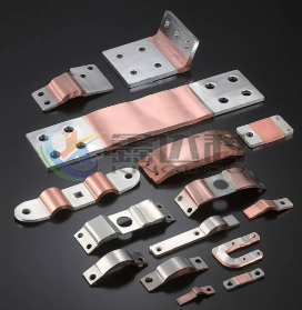
Copper and aluminum busbars are widely used in battery packs. Nowadays, the busbars are mostly made of multilayer copper foil/aluminum foil laminates as the base material, and are fabricated through a...
2026-08-05 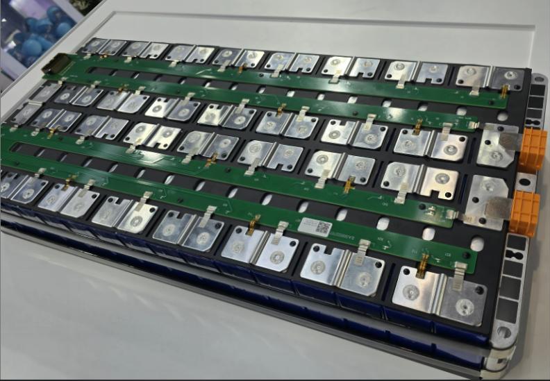
The CCS integrated busbar is mainly composed of signal acquisition components (such as FPC, PCB, FFC, etc.), plastic structural parts, nickel strips, copper busbars, aluminum busbars, etc. These are c...
2025-08-15 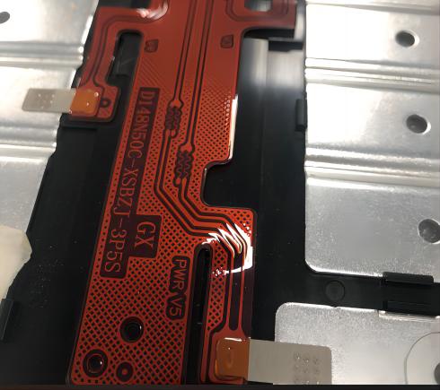
Nickel is a metal with significant industrial value, with a melting point of 1453°C, a boiling point of 3075°C, and a specific gravity of 8.8 g/cm³. It has excellent corrosion resistance, is not easil...
2025-08-15 
Product Name: Power battery soft aluminum busbar, battery module welding flexible connector aluminum busbar, battery soft aluminum busbar Product Material: 1060 O-temper aluminum foil strip, aluminum ...
2023-05-04Phone:
0510-87183933